您好,欢迎进入深圳市颖特新科技有限公司官方网站!
您好,欢迎进入深圳市颖特新科技有限公司官方网站!
/**************************************************************************//**
 * @file     main.c
 * @version  V3.00
 * $Revision: 3 $
 * $Date: 15/09/02 10:03a $
 * @brief    Demonstrate how to set GPIO pin mode and use pin data input/output control.
 * @note
 * Copyright (C) 2013~2015 Nuvoton Technology Corp. All rights reserved.
 *
 ******************************************************************************/
#include "stdio.h"
#include "M451Series.h"
#include "NuEdu-Basic01.h"

#define PLL_CLOCK       72000000


void SYS_Init(void)
{
    /*---------------------------------------------------------------------------------------------------------*/
    /* Init System Clock                                                                                       */
    /*---------------------------------------------------------------------------------------------------------*/

    /* Enable HIRC clock (Internal RC 22.1184MHz) */
    CLK_EnableXtalRC(CLK_PWRCTL_HIRCEN_Msk);

    /* Wait for HIRC clock ready */
    CLK_WaitClockReady(CLK_STATUS_HIRCSTB_Msk);

    /* Select HCLK clock source as HIRC and and HCLK clock divider as 1 */
    CLK_SetHCLK(CLK_CLKSEL0_HCLKSEL_HIRC, CLK_CLKDIV0_HCLK(1));

    /* Enable HXT clock (external XTAL 12MHz) */
    CLK_EnableXtalRC(CLK_PWRCTL_HXTEN_Msk);

    /* Wait for HXT clock ready */
    CLK_WaitClockReady(CLK_STATUS_HXTSTB_Msk);

    /* Set core clock as PLL_CLOCK from PLL */
    CLK_SetCoreClock(PLL_CLOCK);

    /* Enable UART module clock */
    CLK_EnableModuleClock(UART0_MODULE);

    /* Select UART module clock source as HXT and UART module clock divider as 1 */
    CLK_SetModuleClock(UART0_MODULE, CLK_CLKSEL1_UARTSEL_HXT, CLK_CLKDIV0_UART(1));

    /*---------------------------------------------------------------------------------------------------------*/
    /* Init I/O Multi-function                                                                                 */
    /*---------------------------------------------------------------------------------------------------------*/

    /* Set PD multi-function pins for UART0 RXD(PD.6) and TXD(PD.1) */
    SYS->GPD_MFPL &= ~(SYS_GPD_MFPL_PD6MFP_Msk | SYS_GPD_MFPL_PD1MFP_Msk);
    SYS->GPD_MFPL |= (SYS_GPD_MFPL_PD6MFP_UART0_RXD | SYS_GPD_MFPL_PD1MFP_UART0_TXD);

}

void UART0_Init()
{
    /*---------------------------------------------------------------------------------------------------------*/
    /* Init UART                                                                                               */
    /*---------------------------------------------------------------------------------------------------------*/
    /* Reset UART module */
    SYS_ResetModule(UART0_RST);

    /* Configure UART0 and set UART0 baud rate */
    UART_Open(UART0, 115200);
}

/*---------------------------------------------------------------------------------------------------------*/
/*  Main Function                                                                                          */
/*---------------------------------------------------------------------------------------------------------*/
int32_t main(void)
{

    /* Unlock protected registers */
    SYS_UnlockReg();

    /* Init System, peripheral clock and multi-function I/O */
    SYS_Init();

    /* Lock protected registers */
    SYS_LockReg();

    /* Init UART0 for printf */
    UART0_Init();

    printf("Key1 ~ Key4 detection:\n");

    Open_Seven_Segment();
    Initial_Key_Input();
    while(1)
    {

            if(Get_Key_Input()&0XFF)
            {
            if(Get_Key_Input()&0x01)
            {
            Show_Seven_Segment(0,1);
            }
            if(Get_Key_Input()&0x02)
            {
            Show_Seven_Segment(2,1);
            }
            if(Get_Key_Input()&0x04)
            {
            Show_Seven_Segment(4,1);
            }
            if(Get_Key_Input()&0x08)
            {
            Show_Seven_Segment(8,1);
            }

            }


            //Show_Seven_Segment(Get_Key_Input(), 1);


    }

}
这是我设计的一个小程序基于M451的库函数,可以下载到板子上试一试,努力去学习思考,反复验证,
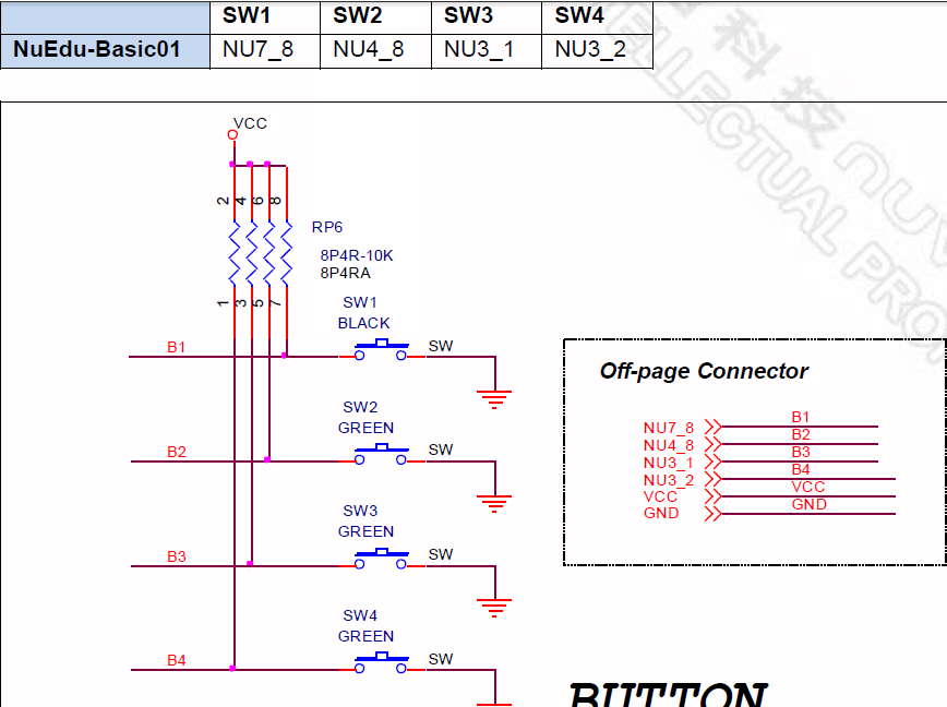
当SW1按上时,B1出电压为零。
我在把库函数贴出来
#include <stdio.h>
#include "M451Series.h"
#include "NuEdu-Basic01_Button.h"
#define KEY1 PE2
#define KEY2 PA8
#define KEY3 PB6
#define KEY4 PB7
void Initial_Key_Input(void)
{
    GPIO_SetMode(PE, BIT2, GPIO_MODE_INPUT);//设为输入
    GPIO_SetMode(PA, BIT8,  GPIO_MODE_INPUT);
    GPIO_SetMode(PB, BIT6, GPIO_MODE_INPUT);
    GPIO_SetMode(PB, BIT7, GPIO_MODE_INPUT);
}

unsigned char Get_Key_Input(void)
{
    unsigned char temp = 0;
    if(KEY1 == 0)
        temp |= 0x1;


    if(KEY2 == 0)
        temp |= 0x2;


    if(KEY3 == 0)
        temp |= 0x4;


    if(KEY4 == 0)
        temp |= 0x8;

    return   temp;
}
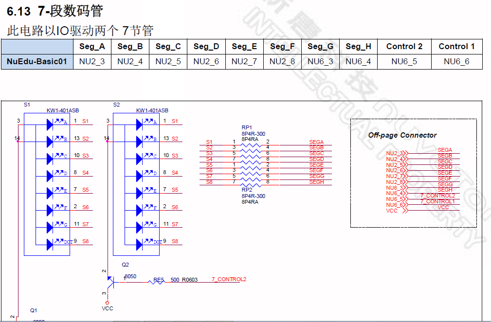
/**************************************************************************//**
 * @file     NuEdu-Basic01_7_Segment.c
 * @version  V3.00
 * $Revision: 4 $
 * $Date: 15/09/02 10:02a $
 * @brief    M451 series NuEdu Basic01 7-Segment driver source file
 *
 * @note
 * Copyright (C) 2014~2015 Nuvoton Technology Corp. All rights reserved.
*****************************************************************************/

#include <stdio.h>
#include "M451Series.h"
#include "NuEdu-Basic01_7_Segment.h"

#ifdef __cplusplus
extern "C"
{
#endif

/** @addtogroup M451_Device_Driver M451 Device Driver
  @{
*/

/** @addtogroup NuEdu-Basic01_7_Segment Driver
  @{
*/


/** @addtogroup NuEdu-Basic01_7_Segment Exported Functions
  @{
*/


/**
  * @brief  Configure the 7-Segment module
  *
  * @param[in]  None
  *
  * @return     None
  *
  * @details    Configure GPIOs of 7-Segment as output mode and turn off all 7-Segement..
  */
void Open_Seven_Segment(void)
{
    GPIO_SetMode(PB, BIT11, GPIO_MODE_OUTPUT);//设为输出
    GPIO_SetMode(PB, BIT12, GPIO_MODE_OUTPUT);
    GPIO_SetMode(PB, BIT13, GPIO_MODE_OUTPUT);
    GPIO_SetMode(PB, BIT14, GPIO_MODE_OUTPUT);
    GPIO_SetMode(PB, BIT15, GPIO_MODE_OUTPUT);
    GPIO_SetMode(PB, BIT5, GPIO_MODE_OUTPUT);
    GPIO_SetMode(PD, BIT11, GPIO_MODE_OUTPUT);
    GPIO_SetMode(PF, BIT2, GPIO_MODE_OUTPUT);
    GPIO_SetMode(PD, BIT8, GPIO_MODE_OUTPUT);
    GPIO_SetMode(PC, BIT8, GPIO_MODE_OUTPUT);

    SEG_A_OFF;
    SEG_B_OFF;
    SEG_C_OFF;
    SEG_D_OFF;
    SEG_E_OFF;
    SEG_F_OFF;
    SEG_G_OFF;
    SEG_H_OFF;
}


/**
  * @brief  Show number at 7-Segment module
  *
  * @param[in]  no The number that will be showed at the specified 7-Segment module.
  * @param[in]  number The group number of the specified 7-Segment module.
  *
  * @return     None
  *
  * @details    Configure GPIOs of 7-Segment to show number at 7-Segment module
  */
void Show_Seven_Segment(unsigned char no, unsigned char number)
{
    SEG_A_OFF;
    SEG_B_OFF;
    SEG_C_OFF;
    SEG_D_OFF;
    SEG_E_OFF;
    SEG_F_OFF;
    SEG_G_OFF;
    SEG_H_OFF;
    SEG_CONTROL1_OFF;
    SEG_CONTROL2_OFF;
    switch(no)
    {
        //show 0
        case 0:
            SEG_A_ON;
            SEG_B_ON;
            SEG_C_ON;
            SEG_D_ON;
            SEG_E_ON;
            SEG_F_ON;

            break;

        //show 1
        case 1:
            SEG_B_ON;
            SEG_C_ON;
            break;

        //show 2
        case 2:
            SEG_A_ON;
            SEG_B_ON;
            SEG_G_ON;
            SEG_E_ON;
            SEG_D_ON;
            break;

        //show 3
        case 3:
            SEG_A_ON;
            SEG_B_ON;
            SEG_G_ON;
            SEG_C_ON;
            SEG_D_ON;
            break;

        //show 4
        case 4:
            SEG_F_ON;
            SEG_B_ON;
            SEG_G_ON;
            SEG_C_ON;
            break;

        //show 5
        case 5:
            SEG_A_ON;
            SEG_F_ON;
            SEG_G_ON;
            SEG_C_ON;
            SEG_D_ON;
            break;

        //show 6
        case 6:
            SEG_A_ON;
            SEG_F_ON;
            SEG_E_ON;
            SEG_G_ON;
            SEG_C_ON;
            SEG_D_ON;
            break;

        //show 7
        case 7:
            SEG_A_ON;
            SEG_B_ON;
            SEG_C_ON;
            SEG_F_ON;
            break;

        //show 8
        case 8:
            SEG_A_ON;
            SEG_B_ON;
            SEG_C_ON;
            SEG_D_ON;
            SEG_E_ON;
            SEG_F_ON;
            SEG_G_ON;
            break;

        //show 9
        case 9:
            SEG_A_ON;
            SEG_B_ON;
            SEG_C_ON;
            SEG_F_ON;
            SEG_G_ON;
            break;
    }

    switch(number)
    {
        case 1:
            SEG_CONTROL1_ON;
            break;

        //show 1
        case 2:
            SEG_CONTROL2_ON;
            break;
    }
}


/*@}*/ /* end of group NuEdu-Basic01_7_Segment_EXPORTED_FUNCTIONS */

/*@}*/ /* end of group NuEdu-Basic01_7_Segment_Driver */

/*@}*/ /* end of group M451_Device_Driver */

#ifdef __cplusplus
}
#endif

/*** (C) COPYRIGHT 2014~2015 Nuvoton Technology Corp. ***/
多看看库函数,对你的编程有很大的提高
/*---------------------------------------------------------------------------------------------------------*/
/* 7-Segment GPIO constant definitions                                                                           */
/*---------------------------------------------------------------------------------------------------------*/
#define SEG_A_ON            PB11=0    /*!< 7_Segment setting for turning on 7-Segment A. */
#define SEG_B_ON            PB12=0    /*!< 7_Segment setting for turning on 7-Segment B. */
#define SEG_C_ON            PB13=0    /*!< 7_Segment setting for turning on 7-Segment C. */
#define SEG_D_ON            PB14=0    /*!< 7_Segment setting for turning on 7-Segment D. */
#define SEG_E_ON            PB15=0    /*!< 7_Segment setting for turning on 7-Segment E. */
#define SEG_F_ON            PB5=0    /*!< 7_Segment setting for turning on 7-Segment F. */
#define SEG_G_ON            PD11=0    /*!< 7_Segment setting for turning on 7-Segment G. */
#define SEG_H_ON            PF2=0    /*!< 7_Segment setting for turning on 7-Segment H. */
#define SEG_CONTROL1_ON        PD8=1    /*!< 7_Segment setting for turning on 7-Segment C1. */
#define SEG_CONTROL2_ON        PC8=1    /*!< 7_Segment setting for turning on 7-Segment C2. */


#define SEG_A_OFF            PB11=1    /*!< 7_Segment setting for turning off 7-Segment A. */
#define SEG_B_OFF            PB12=1    /*!< 7_Segment setting for turning off 7-Segment B. */
#define SEG_C_OFF            PB13=1    /*!< 7_Segment setting for turning off 7-Segment C. */
#define SEG_D_OFF            PB14=1    /*!< 7_Segment setting for turning off 7-Segment D. */
#define SEG_E_OFF            PB15=1    /*!< 7_Segment setting for turning off 7-Segment E. */
#define SEG_F_OFF            PB5=1    /*!< 7_Segment setting for turning off 7-Segment F. */
#define SEG_G_OFF            PD11=1    /*!< 7_Segment setting for turning off 7-Segment G. */
#define SEG_H_OFF            PF2=1    /*!< 7_Segment setting for turning off 7-Segment H. */
#define SEG_CONTROL1_OFF    PD8=0    /*!< 7_Segment setting for turning off 7-Segment C1. */
#define SEG_CONTROL2_OFF    PC8=0    /*!< 7_Segment setting for turning off 7-Segment C2. */
按键设为输入,断码管设为输出。
轻触开关的功能分为两种:一个是常开型、一种是常闭型。最为常见的是常开型,常开型是指线路一般为断开,轻按按键柄触动弹片和底座的炮点接触,这时开关视为导通,放开按键柄弹片和炮点分开,这时开关视为分开,产品的性能为OK。线路断开时两路的阻值为30m欧,当开关导通时两路的接触电阻0,这时开关性能就是非常好的。常闭型是比较少见的,因为这样比较不符合常规的产品设计,常闭型是指正常情况下开关是导通的,当触动开关的时候,线路和功能都是为断开的。这种开关的阻值就是和常开的相反,所以一般不推荐使用。下图都是常开轻触开关:

不论是常开型还是常闭轻触开关必须由两个引脚以上组成,这样才能形成一组开关功能,正常为两脚、四脚、五脚。为什么会有五脚开关的呢?因第五只脚是用来接地的,接地脚是用来干嘛的我想大家都知道。当然还有三个脚的,一般三脚都是侧压的比较多,这个第三只脚就是为了固定设计的,所以大家可以放心使用,使劲的去按压都是没有问题的。下图中两脚线路我们一款就一目了然了,我来解释一下轻触开关的四个引脚是怎么接的吧!正常情况下1和2为一组导通,3和4为一组导通,当触动开关的时候的1和3为一组,2和4为一组,按照这样的方式来设计开关的功能就是对的了。
下一篇:UART简介